Assignment 2 | THE FUEL TANK
Yamaha IT250
Fuel Tank

Project Outline
Forming groups of 10 multidisciplinary students, a 1:1 scale model of the Yamaha IT250 fuel tank will be fabricated. As individual students, an aluminium skin will be created to adhere to the construction and detail of the model.
Objectives
3 Metal Shaping


Fuel Tank

Project Outline
Forming groups of 10 multidisciplinary students, a 1:1 scale model of the Yamaha IT250 fuel tank will be fabricated. As individual students, an aluminium skin will be created to adhere to the construction and detail of the model.
Objectives
- Model Construction The creation of a 1:1 fuel tank template to assist with the fabrication process
- Pattern Fabrication Compose a pattern or template which will provide a method of construction and reference for the aluminium skin
- Metal Shaping Using the model and pattern as reference, shape and sculpt the aluminium to adhere closely to the construction of the fuel tank
- Documentation Record the process of fabricating the Yamaha IT250 fuel tank
1 Model Construction
The initial phase of constructing the model involved utilising Photogrammetry to digitally fabricate a 1:1 model. The required 3D model was created through Autodesk Recap, which compiled the range of photographs we collectively captured of the Yamaha IT250 fuel tank and composed the model.
 |
| Thanks to a member of our group, Charlie McLeod, our model was successfully created in Autodesk Recap after lots of photos |
 |
| Our first Photogrammetry attempt was unsuccessful |
The next step involved transferring our created model into Autodesk Slicer. This program divided, or sliced, the model into components which could be used by a laser cutter, and as a group we opted for a tight grid which would enable us to fabricate a more cohesive and accurate model. Adobe Illustrator was then used to organise the templates created by Autodesk Slicer onto a sheet which would be compatible with the laser cutter. Once our files had been formatted correctly we could proceed to laser cutting.
 |
| The laser cut templates were a perfect fit |
 |
Glue was needed to further
strengthen the bondage
|
 |
Our Illustrator files translated
directly onto plywood sheets,
which were then laser cut to
create our waffles
|
 |
Our stack of laser cut
waffles
|
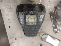
After our files had been laser cut, the next phase of model construction involved compiling the laser cut templates into the correct place to fabricate the model. Glue was used to further join the templates together to ensure structural integrity. Lastly, the
model was covered extensively with masking tape to smooth the exterior and provide a more cohesive finish to assist with the fabrication of the aluminium skin.
 |
| The finished product |
 |
| The complete model |
 |
Masking tape provided
for a smoother finish
|
2 Pattern Fabrication
To assist with the construction of the aluminium skin, patterns of certain parts of the model were created from sheets of paper. Amity Yore, Emma La Coste and Thomas Surmon comprised my team, and as a group of four we divided the model into four correlating components which were:
 |
TOP SIDE AMITY
|
 |
TOP EMMA
|
 |
| SIDE BEN |
 |
| BACK THOMAS |
Following on from this, we began to draw out our paper templates of the described components of the model, which we then cut out using scissors and measured against the model to ensure accuracy. This was rather challenging, as drawing with the 2D nature of paper against our 3D model provided rather inaccurate depictions of the components which meant that multiple efforts to redraw the template was needed. Once we had successfully created our paper templates, we drew these with permanent marker onto our aluminium sheets which could then be ready for cutting.
 |
Drawing the top was
quite a challenge as a
result of the many
dimensions
|
 |
Preparing to trace our pattern
onto the aluminium skin
|
Using a combination of tin-snips, the guillotine and the cutting lever, the templates were cut out with precision and filed along the edges to eliminate undesired effects such as sharp protruding shards and uneven finishes. The result of this was a set of aluminium skins ready for shaping and sculpturing to our model.
 |
Aluminium sheet ready
for tracing
|
 |
Cutting the side template
with the lever
|
 |
Thomas cutting his
template with tin-snips
|
The third component of the project involved shaping our metal to match the construction of our Yamaha IT250 fuel tank model.
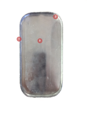
Firstly, I started by analysing the shape of the sides by feeling for general characteristics such as bulges, depressions and curves. From this analysis I discovered that the main components forming the sides of the fuel tank were the following:
- Large bulge towards the back plate
- Depression leading away from this bulge toward the front of the model
- Curves at the top of the side, running adjacent to Amity's section
 |
My analysis of the sides
characteristics
|
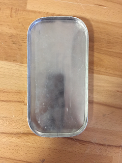
Following on from this, I started the shaping of my templates by stretching the aluminium using the English Wheel to form the bulge. I repeated this method with my corresponding template for the other side of the model. This required patience and persistence, as I was constantly fitting my skin to the model to check how well it was adhering to the shape.
Once the bulge was adhering well, I begun to work on fabricating the depression. This was challenging, as the inverse curve I was trying to create would disfigure the shape of the bulge. I discovered that soft and gentle strikes with a rubber mallet could achieve the depression without affecting the rest of the skin, so I begun to employ this tactic on both of my templates with great success.
Lastly, I begun curving the edges of the skin to adhere correctly to the model, and I achieved this using both the shrinker and a dolly. The shrinker was used to provide a consistent curve along the edge of the skin, and then I used a dolly to exaggerate this curvilinear component.


4 Documentation
My favourite part of the project - documenting both myself and my team's experience of creating the Yamaha IT250 fuel tank with aluminium skins.
This was an enjoyable project which brought with it an array of challenges and rewarding learning curves. The shape of the fuel tank proved harder to manipulate with the aluminium skins than I first thought, however I am glad that we decided to undertake the challenge as I feel a sense of fulfilment with the finished project.
See below for the finished product!


5 Landscape Architecture
This project challenged me in terms of the complexity and the skill involved to achieve a cohesive and fitting aluminium skin. Another element this assignment delivered was the relation I could see between such a task and my field of study, Landscape Architecture. Often in any form of architecture, a lot of time is spent drawing and designing spaces, materials and elements, however often you are not involved in the fabrication process. This task was different - I thoroughly enjoyed being engaged in both aspects of the fuel tank; drawing/designing and then constructing.
The knowledge I have gained through this task in regards to manufacturing and materiality I believe I can take with me with my studies.
Comments
Post a Comment